
// Wait 100 ns for global reset to finishįigure 5.// Instantiate the Unit Under Test (UUT).Verilog Code of the Test Bench of the Full Adder (fullAdder_tb.v).assign Cout = (In1 & In2) | (In2 & Cin) | (Cin & In1).

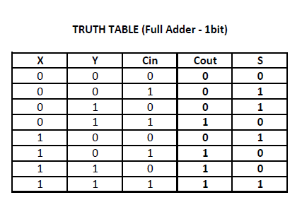
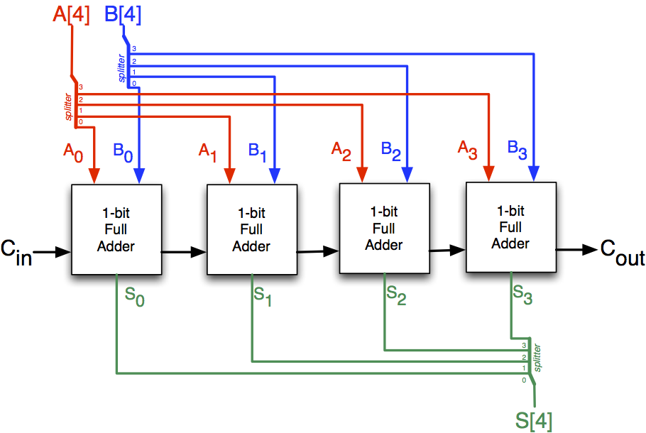
Verilog Code of the Full Adder (fullAdder.v) The 8-bit adder adds the numbers digit by digit, as can be seen in the schematic diagram below.There two output ports as S, and C out which are also 1-bit wide. The module has three 1-bit input ports as A, B, and C in. The Verilog module of full adder is shown in Figure 3. In the truth table A, B and C in are the three input signals and S and C out are the output signals. The truth table of a typical full adder is shown in Figure 2. The gate level design of a full adder is shown in Figure 1.įigure 1. The full adder is usually a component in a cascade of adders, which add 4, 8, 16, 32 bit binary numbers. S = A xor B xor C in C out = (A and B) or (B and C in) or (C in and A) If A and B are two 1-bit values input to the full adder and C in is the carry-in from the preceeding significant bit of the calculation then the sum, S, and the carry-out, C out, can be determined using the following Boolean expressions.

A full adder adds two 1-bit binary numbers along with 1-bit carry-in thus generating 1-bit sum and 1-bit carry-out.


 0 kommentar(er)
